
Ultrasonic Humidifier Control Board: Transducer & Dry-Burn Protection
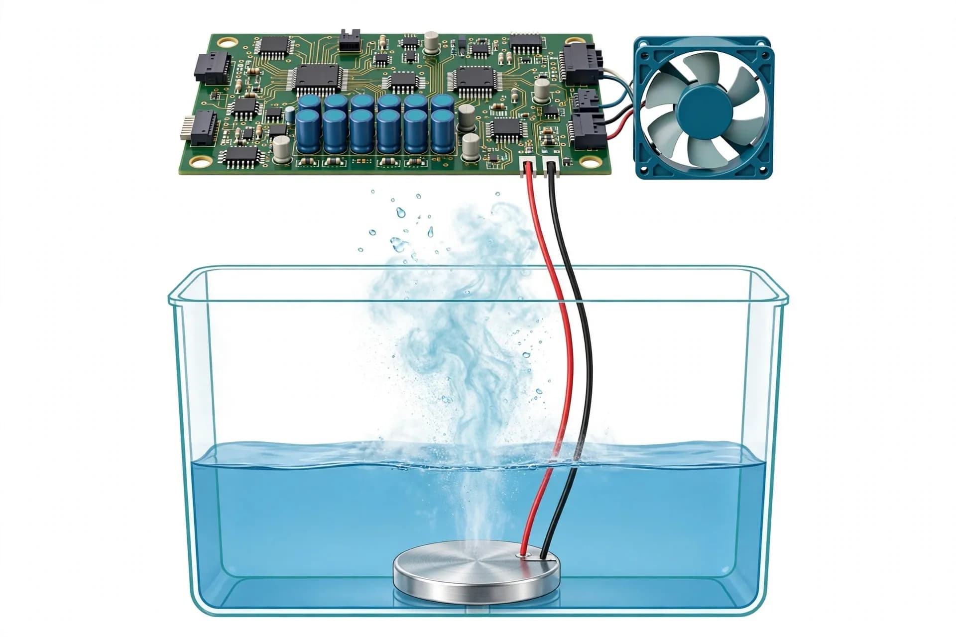
Stable mist, no dry burning, smooth mist-level switching — most of it comes down to the control board. This article breaks down transducer selection, frequency tracking, and dry-burn protection.
Whether an ultrasonic humidifier produces stable mist, avoids dry burning, and switches mist levels smoothly comes down to one thing in most cases: the control board. This article takes apart a typical humidifier control board — how to choose the transducer, why the drive circuit needs frequency tracking, and why water-level detection must be the highest-priority protection.
1. What the Control Board Does in the Whole Machine
Strip a humidifier down, and the control board's job is one chain:
Power → Main MCU → Atomizer drive → Transducer produces mist → Fan pushes the mist out
At the same time it has to watch three things: tank water level, ambient temperature and humidity, and user input from buttons or touch keys. When the water level is too low, the machine must stop atomizing first — more on that below.
A typical reference design (Holtek's 1.7 MHz / 24 V / 20 W humidifier solution) splits the hardware into a power supply circuit, an atomizer drive and frequency-tracking circuit, a fan drive circuit, a capacitive water-detection circuit, and a potentiometer mist-adjustment circuit. Most mass-production boards look similar; the main differences are the MCU choice and how complete the protection is.
2. The Transducer: 1.7 MHz vs. 2.4 MHz
The transducer is a piezoelectric ceramic disc. Powered up, it vibrates at megahertz-range frequencies and breaks the water near the surface into micron-scale mist. The accepted explanation combines cavitation and capillary-wave theory: the vibration is so fast that the water cannot follow the vibrating surface, so momentary vacuum and strong compression alternate, cavitation bubbles form and collapse, capillary waves shatter, and droplets about 1 micron in diameter break the water's surface tension and enter the air.
The two most common frequency specs compare as follows (figures from one transducer vendor's datasheet; they vary by manufacturer, so always verify with real samples when selecting):
Drive power: 1.7 MHz approx. 23 W; 2.4 MHz approx. 12 W.
Atomization rate: 1.7 MHz over 400 ml/h; 2.4 MHz over 200 ml/h.
Working water depth: 1.7 MHz 30–35 mm; 2.4 MHz 18–30 mm.
Droplet size: 1.7 MHz relatively coarse; 2.4 MHz relatively finer.
The selection logic is straightforward:
- For high mist output and large coverage, pick 1.7 MHz. Its droplets are relatively coarser, but it delivers far more mist per hour — right for living rooms and bedrooms.
- For fine mist, low power, and small desktop units, pick 2.4 MHz. The mist is finer and drive power is roughly half — right for small tanks and low-power products.
- Don't ignore the water-depth requirement. Transducers are sensitive to water depth: too deep, and the vibration energy never reaches the surface, so mist output drops; too shallow, and the transducer is exposed and dry-burns. Each spec has a different working depth range, so the tank depth must be set to match the chosen transducer — never fix the enclosure first and pick the transducer later.
There is also a mesh-type (micro-hole) atomizer family working around 100 kHz, which vibrates a perforated metal mesh to push water through the holes as mist. It runs at just 3–5 V and doesn't need to sit underwater. Aroma diffusers and car mini-humidifiers commonly use this approach — a different route from the immersed ceramic discs above.
3. The Drive: Why Frequency Tracking Is Necessary
A transducer does not keep working well on a fixed frequency. Its resonant point drifts with temperature, water level, and aging. Drive it off resonance and mist output falls, power consumption rises, and in the worst case the drive transistor overheats and the transducer ages faster.
So production designs generally implement frequency tracking:
- At power-up, the MCU sweeps the PWM output frequency from high to low.
- A current-sampling circuit measures the drive current in real time.
- When the current reaches its target value, that frequency is registered and locked in as the operating frequency.
This approach comes from Holtek's reference design. The principle is simple but effective: the point of maximum current is close to the resonant point. A board without frequency tracking may be tuned perfectly at the factory and still drift out of tune after weeks of use — mist output fading, and returns climbing with it.
On drive topology, the common structure is MCU PWM → MOSFET → inductor boost → transducer. Two points matter:
- Leave enough heatsinking for the MOSFET. The atomizer drive is a high-current loop; undersize the transistor or the heatsink and the drive stage is what fails first at high temperature.
- Isolate the atomizer supply from the MCU supply. The atomizer loop is noisy, and sharing a supply with the low-voltage side can reset the MCU — the classic symptom is a machine that reboots for no apparent reason.
4. Dry-Burn Protection: Why Water-Level Detection Is Top Priority
One humidifier patent states it plainly: the water-level sensor has the highest priority and can directly determine whether the circuit runs. The reason is simple: a transducer running dry can be damaged within tens of seconds, and dry burning is the machine's most direct safety risk.
Three common water-level detection methods:
- Float + reed switch: reliable and cheap, the most common in mass production. The float rises and falls with the water level, and the reed switch gives the MCU a clean on/off signal. The downside is the mechanical structure — long-term use needs attention to limescale jamming.
- Capacitive detection: no moving parts; mounted on the tank's outer wall or built into the board, it detects the water level from capacitance change. Holtek's reference design uses capacitive detection. It resists limescale better, but the circuit needs more careful tuning.
- Electrode / resistive: detects water by its conductivity. Low cost, but sensitive to water quality — it can misjudge purified water, whose conductivity is low.
Whichever method is used, the firmware logic should be the same: low water → stop atomizing immediately → light the low-water indicator (or sound the buzzer). This decision must not go through a slow polling loop or get blocked by other tasks. Some designs add over-temperature protection on top: abnormal transducer temperature also stops the machine immediately.
5. The Rest: Power, Fan, Closed Loop, and Interaction
- Power: typically a 24 V adapter comes in — one rail feeds the atomizer drive directly, one is stepped down to 12 V for the fan, and one to 5 V / 3.3 V for the MCU and sensors. Leave headroom in the supply; the atomizer's inrush current at startup is not small.
- Fan: it blows the mist out of the tank. Production designs mostly use 12 V fans, with the MCU adjusting speed by PWM across three levels matched to the mist setting. If the fan is too weak, mist pools at the outlet, condenses, and drips.
- Temperature/humidity closed loop: machines with an auto mode add a temperature/humidity sensor (I2C parts like the SHT30 or AHT20 are common), placed at the air inlet away from the mist. The logic: start misting below the target humidity, stop above it. Never mount the sensor near the mist outlet — it will read 99% forever and the machine will never stop.
- Interaction: buttons, touch keys, knobs, 7-segment or OLED displays. Connected models add a Wi-Fi / Bluetooth module for app control and OTA updates.
6. From a PCBA Viewpoint: Where Mass Production Trips Up
From board-making experience, the most common problems with humidifier control boards in production:
- Transducer consistency. Transducers are piezoelectric ceramic parts, and resonant frequency varies between batches. Without frequency tracking, the first batch can be fine and the second batch's mist output different. Frequency tracking is not a nice-to-have — it is a mass-production consistency requirement.
- Limescale and corrosion. A transducer sits in water long-term; limescale builds up on the surface and mist output fades gradually. What the board can do is enforce strict dry-burn protection and make the structure easy for users to clean. Don't design assuming users will always use purified water.
- Moisture ingress. The inside of a humidifier is humid. If the control board sits too close to the tank without conformal coating, solder joints corrode over time and leakage-current problems follow. Keep the layout away from the water path and protect the critical areas.
- EMC. The atomizer drive is high-frequency and high-current, so both radiated and conducted emissions can exceed limits. Inductor choice, routing, and grounding need to be handled at layout stage — fixing them at certification-test time is expensive.
Conclusion
A humidifier control board comes down to three things: pick the right transducer frequency, implement frequency tracking in the drive, and make dry-burn protection the highest priority. Get those three right, and the rest — power, fan, sensors, interaction — are mature building blocks. That is what machine stability and low return rates rest on.
Sources
Transducer specs (UT Transducer specification page); cavitation and capillary-wave theory (Makers Electronics); frequency tracking and capacitive water detection (Holtek WAS-1995EN reference design); water-level sensor top priority (patent CN111678234A); MOSFET drive and water-level options (STM32-based smart humidifier open-source design). Atomization rate, drive power and similar figures are quoted from vendor datasheets and vary by manufacturer and batch — verify by measurement when selecting parts.